Manufacturers who supply or receive pre-machined manufactured components, including molds, often ask, “Will this part clean up?” Oftentimes, this question of part clean-up can make or break an order, a job or a delivery schedule, and although the respondent can vary from a supplier to the downstream customer or both, the question must be answered.
Achieving a confident answer through inspection and layout activity is often difficult and time-consuming. However, the use of CAD data and 3D digitizing technology can significantly improve overall accuracy, effectiveness and efficiency, resulting in the potential answer to this critical question.
Most critical, pre-finished components are subject to various forms of inspection or layout. As manufacturers continue to strive for nearer-net-shape molds, castings, forgings and fabrications, this process becomes more detailed and subject to scrutiny. There could be dozens of complex inspection criteria (diameters, positions, angles, etc.) that must be satisfied before components are acceptable to the customer and viable for post-processing.
Satisfying all the inspection criteria can create issues such as: 1) difficulty in conducting proper inspection, requiring multiple tools, tolerance stack-ups, etc.; 2) multiple interpretations of inspection data by the supplier and customer; 3) multiple (and differing) inspection methods used by the supplier and customer; 4) significant non-value-added time in the part’s value stream; 5) errors that can lead to unnecessary part rejection, scrapping of parts once on the machine and unnecessary re-work; and 6) unnecessary addition of safety stock on components to ensure their acceptance. This can also generate unnecessary waste in raw material, increased energy required to provide pre-finished components and additional material removal.
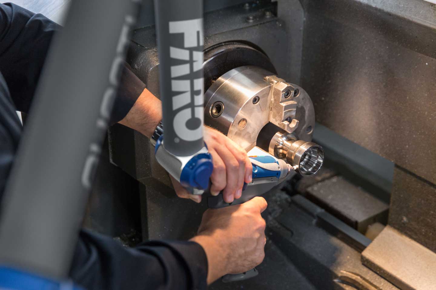
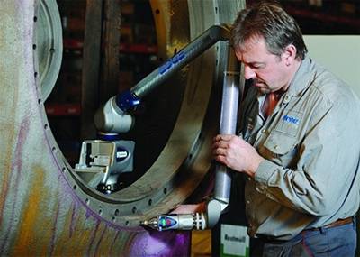 These potential issues have driven manufacturers to search for a more effective inspection/measurement solution. One is the use of finished-part CAD data in conjunction with a 3D digitizer (laser scanner, photogrammetry, imaging systems, CMM with rapid-probing, etc.). The 3D measurement system can be used to collect data in all critical areas of the supplied component, then 3D measurement software is used to compare this collected data to the finished part model. This is a slight variation from the traditional method of comparing a pre-finished part to its pre-finished model (or print). However, comparing to finished geometry allows the supplier or customer to quickly and clearly see where the pre-finished component has either too much or too little stock.
Too much stock. This can lead to wasted machine hours and unnecessary material scrap. It could also be an indication that the upstream process (mold, casting, etc.) needs to be altered to reduce excess raw material (reducing costs and scrap, etc.). At the very least, the excess stock can be accounted for in the shop’s schedule and in the lead time given to the customer.
Too little stock. This could mean that the ideal finished part will not be realized from the supplied component, so the component should not be set up on the machine to avoid generating a scrapped part. It could also mean that the component must go through remediation before it can be post-processed. Either way, the parties involved have a heads-up on this condition and can make decisions without incurring further scrap or delays.
Re-alignment/re-layout. If the part analysis to CAD shows heavy in some areas and light in others, there may be an opportunity to save these components by digitally re-aligning the part to the CAD. Many available software packages (with varying degrees of ease and effectiveness) can digitally best-fit the collected part data to the finished CAD model. This can transform a part that was considered in failing condition and allow it to proceed through the value stream. The amount of data, and ultimately the 3D hardware/software solution, required to get a good part analysis to CAD will vary from part to part, based on geometry, complexity and tolerance. However, employing CAD data and 3D digitizing can be a fast, effective and almost error-proof solution for suppliers and downstream manufacturers.
Article
Inspection/measurement – will this part clean up?
Article
Manufacturing
Quality Control & Inspection
Aerospace
Automotive
Education
Energy & Natural Resources
Heavy Equipment
Measurement Service Providers
Metalworking, Machining & Assembly
Rubber and Plastics
Shipbuilding
Portable Measurement Arms
Quantum
Quality Control & Inspection (BP)
Awareness
Best Practices