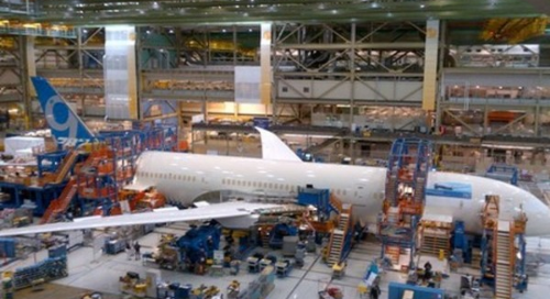
Figure 1. Final Assembly of Boeing Dreamliner
Aerospace assembly is the finest jewel among assembly applications. It presents a daunting and unique challenge: The assembly of very large structures to very close tolerances along with huge fastening and drilling operations.
Assembly can take up to as much as 40% of the total cost of manufacturing an airframe due to the labour and quality issues because of drilling thousands of holes per aircraft. Around 5% of the total manufacturing cost of an aircraft or 10% of the airframe cost is caused by the use of fixed tooling.
The manufacturing process of Airbus wings requires the drilling of over 40 million holes in aircraft structures per annum. The majority of these holes, approximately 80% of the total, were drilled manually.
This tremendous amount of drilling and fastening, along with demanding tolerances makes aerospace assembly one of the most challenging but at the same time exciting fields in aerospace manufacturing. The goal of this series is to present the most recent innovation trends in aerospace assembly with real life examples.
TREND 1. MEASUREMENT ASSISTED ASSEMBLY: The Race to Decrease Tooling Costs and Assembly Time
The general technological trend in aerospace assembly is in the direction of less and less use of tooling. The ideal final condition would be “The best tool is no tool at all”, a situation where the use of tools is absolutely minimized.
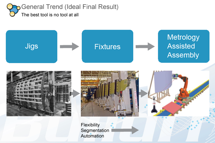
Figure 2. General Trend in Aerospace Assembly
We can analyze this trend in three distinct phases:
1. Jigs
In conventional assembly, most of the tooling is “fixed tooling”: They are monolithic jigs dedicated to a specific set of product. If a new product is required to be assembled, you have to build an entirely new tooling set. The fixed tooling also requires periodic certifications to check their accuracy to satisfy assembly tolerances. Therefore the traditional approach causes a huge drain on time and cost.
A jig determines both the location of the assembly and the position of assembly features such as holes.
2. Fixtures (Jigless Assembly)
The major difference between a jig and a fixture is that a fixture locates assembly, but it does not determine the position of features as a jig does. Therefore fixtures are much simpler than jigs and they offer more flexibility. The fixtures can also be reconfigured by the use of actuators equipped with servomotors according to product specifications.
3. Measurement (Metrology) Assisted Assembly
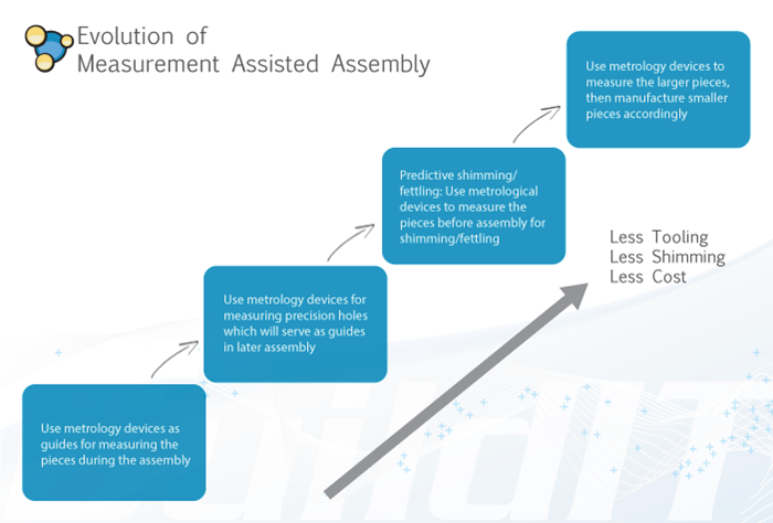
Figure 3. Evolution of Measurement Assisted Assembly
As we shall see in the next sections, there are several forms of measurement (metrology) assisted assembly. But the most general form can be summarized as the guidance of assembly completely by measurement devices, without any use of precise tooling. This approach provides maximum flexibility and repeatability. The evolution of measurement assisted assembly is summarized on Figure 3. It can be seen that conforming to the general trend, the direction of evolution is towards less tooling and hence less complexity and less cost.
Advantages of Metrology Assisted Assembly
- Reduction of cost of tooling
- Increase in repeatability of assembly
- Improvement in the achievement of tolerances
Are you decreasing your use of jigs/fixtures and moving towards metrology to assist in your assembly procedures? Let us know in the comments below, and join us next time when we delve into using measurement devices for providing guidance for assembly.
Sources:
- Muelaner, J.E. and Maropulos, P.G., 2008. Large Scale Metrology In Aerospace Assembly. In: 5th International Conference on Digital Enterprise Technology, 2008-10-22 – 2008-10-24, Nantes.
- Kihlman, Henrik, Affordable automation for airframe assembly : developing of key enabling technologies. – Linköping, 2005. – (Linköping Studies in Science and Technology. Dissertations ; 953)
- Latger, F., Harris, T., and Björklund, S., “Drilling Cost Model,” SAE Technical Paper 2002-01-2632, 2002, doi:10.4271/2002-01-2632.
- Muelaner, J.E. and and Maropulos, P.G., 2010. Design for Measurement Assisted Determinate Assembly (MADA) of Large Composite Structures. Journal of the Coordinate Metrology Systems Conference