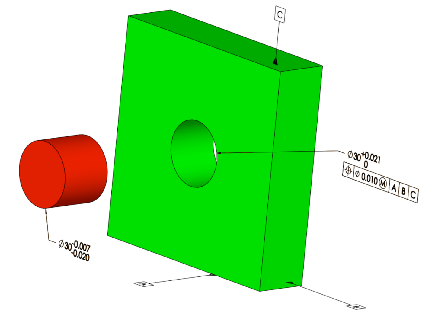
Figure 1. Part with Maximum Material Modifier: As the designed fit is for a looser tolerance fit, the maximum material modifier becomes more appropriate.
The use of material modifiers in GD&T may seem quite abstract for beginners. When should we use MMC (Maximum Material Condition), LMC (Least Material Condition) and RFS (Regardless of Feature Size)? What are the practical implications of these modifiers? This text emphasizes the relationship between material modifiers and fit conditions. Take note that this is just a conceptual introduction and that each application should be considered in its particular circumstances.
Fits
Fits between cylindrical features (holes and pins) define the proper assembly of many mechanisms. ISO standard [1] defines three main kinds of fits:
- Clearance fit: There is always a clearance between the hole and the pin. The lower limit of the hole is always bigger than the higher limit of the pin.
- Transition fit: Fit that can provide a clearance or an interference after the assembly.
- Interference fit: There is always an interference between the hole and the pin. The upper limit of the hole is always smaller than the lower limit of the pin.
Material Modifiers and Fits
MMC: More Clearance, Looser Fit
Design Intent: Easier Assembly (Implied: Less Location Accuracy)
Worst Case Condition for Assembly: Maximum material condition
The design intent of the maximum material modifier being easy and guaranteed assembly, we don’t care if the mating pin wiggles around a bit after assembly. So we encourage the hole to be larger, putting a maximum material limit.
As the hole gets larger in size (hence moving from maximum material condition toward least material condition), it provides a looser fit with the mating pin. The clearance gained can be used as a bonus tolerance for position tolerance.
LMC: Less Clearance, Tighter Fit
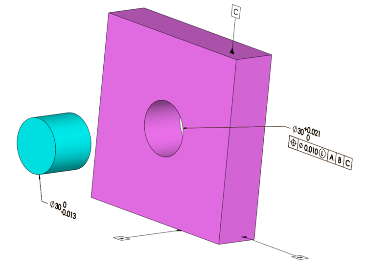
Figure 2. Part with Least Material Modifier: As the designed fit gets tighter (Pin tolerance decreased with respect to the one in Figure 1), the least material modifier becomes more appropriate.
Design Intent: More Location Accuracy (Implied: Less Easy Assembly)
Worst Case Condition for Location Accuracy: Least material condition
The design intent of the least material modifier being more location accuracy, we don’t want the mating pin to wiggle around so much after assembly. So we encourage the hole to be smaller, putting a least material condition.
As the hole gets smaller in size, it provides a tighter fit with the mating pin. The tightness gained can be used as a bonus tolerance for position tolerance.
The use of LMC can pose some risk in the assembly, as it is difficult to design and manufacture the correct tightness limit for the assembly (as opposed to looseness limit in the MMC case). If the hole gets too small, we can end up getting an unwanted interference fit.
RFS: No Clearance, Interference Fit
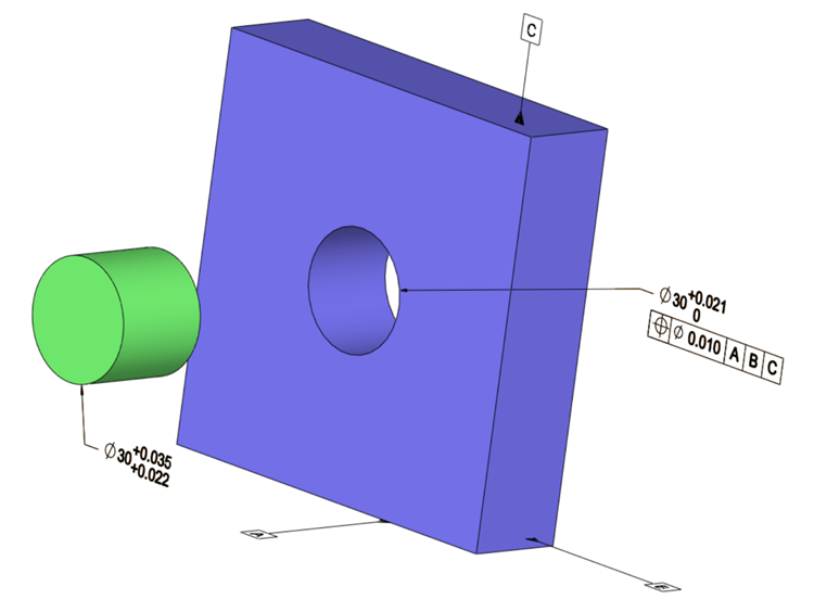
Figure 3. Part with Regardless of Feature Size Condition: As the location accuracy is of the utmost importance, there is no relationship between the hole size and the position tolerance (Pin tolerance indicates a press fit and no clearance).
Design Intent: High and Robust Location Accuracy
The design intent of the Regardless of Feature Size condition is the location accuracy. Once the pin is press fit into the hole, the position of the pin is determined and it cannot wiggle at all.
The size of the hole has no relationship with the location of the hole. If the hole size gets larger or smaller, there is no bonus added to position tolerance.
Summary
Hence, we could summarize the relationship between hole size and relative bonus tolerance as follows:
- MMC: As the hole gets larger, bonus tolerance increases,
- LMC: As the hole gets smaller, bonus tolerance increases.
- RFS: There is no relationship between the hole size and the bonus tolerance.
References
- ASME Y 14.5-2009 , Dimensioning and Tolerancing. New York: American Society of Mechanical Engineers.
- ISO 286-1:2010, Geometrical product specifications (GPS) — ISO code system for tolerances on linear sizes — Part 1: Basis of tolerances, deviations and fits