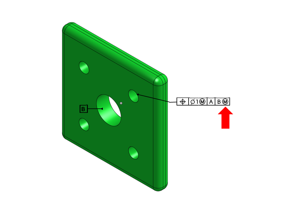
Figure 1. The annotation B(M) on this figure indicates a maximum material boundary applied on datum feature B
The goal of this blog post is to present the maximum material boundary (MMB) concept in GD&T applications. The maximum material boundary concept is simply the use of a maximum material condition on a datum feature, as shown in Figure 1 (the annotation B(M)). Its major use is to allow easier assembly conditions on a part.
To fully understand the maximum material boundary concept, we need to understand a more fundamental concept: the datum reference frame (DRF) (Figure 2).
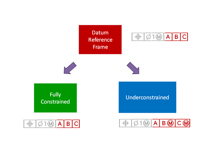
Figure 2. Datum reference frame concept in GD&T
Datum Reference Frame: A three-dimensional Cartesian coordinate system that defines the product. Dimensions and tolerances all originate from the DRF.
Fully Constrained: When fully constrained, the part to be evaluated is completely immobilized: all degrees of freedom of the part are locked. To physically immobilize a part, we can use datum feature simulators, such as a chuck, a mandrel or a vise, on the datum features.
Underconstrained: When underconstrained, the part has conditional mobility. We’ll get into more details on this, but the main point is that the part has some freedom to move; it is not completely immobilized. A part with datums that have been assigned material modifiers, or that has less than 3 datums, can generally be considered to be underconstrained.
Why to define a DRF with the underconstrained condition: The main advantage of the MMB Concept is that it facilitates assembly. The part can rattle around or wiggle as long as the MMB allows it, and this helps tolerances to pass.
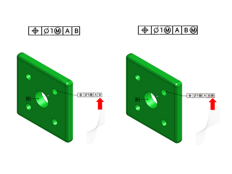
Figure 3. Both of the parts are underconstrained. The difference is that the one on the right has a secondary datum feature with a material boundary modifier
Underconstrained (Figure 3, Left)
Both of the datums are defined at RMB (Regardless of material boundary). This part is still underconstrained: The specifications allow rotation around B since there is no datum C to stop the rotation (there could have been a slot or a keyway).
Underconstrained + Maximum Material Boundary Modifier on Datum B (Figure 3, Right)
This time, the datum B is defined at the MMB: This allows Rotation + Translation around the axis of datum B.
What would be the effect of this modifier? Let’s take a look at Figure 4, which shows the underconstrained parts with corresponding gages:
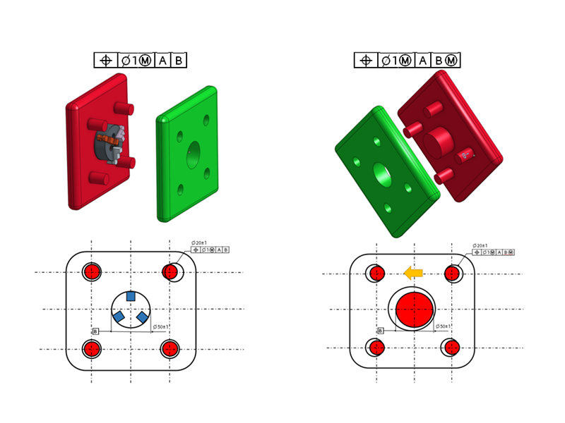
Figure 4. Underconstrained parts with corresponding gages.
Underconstrained (Figure 4, Left)
If we use a chuck on datum feature B to immobilize the part, the part is completely fixed with respect to datum feature B.
Now, let’s imagine one of the holes is in the wrong position in translation (Figure 4, bottom-left). As the part is not allowed to translate in this condition, there is nothing we can do; the part would not pass the inspection since the tolerance wouldn’t pass.
Since the chuck is firmly holding the part in translation, no shift of the pattern of holes (there is no wiggle room on the part) is allowed for this degree of freedom.
Underconstrained + Material Modifier on B (Figure 4, Right)
With an underconstrained part with a material modifier, we can use a fixed gage on B (Figure 4, bottom-right). The dimension of this gage is defined by the MMB of datum feature B: It corresponds to smallest possible hole diameter for datum B.
If the hole for datum B were manufactured at less than its MMB condition, causing it to increase in size, we would have extra mobility (Figure 4, bottom-right). This extra mobility would give us wiggle room during the inspection, allowing the part to pass.
Conclusion
The concept of the maximum material boundary condition is very useful since it can allow much easier assembly conditions. As the datum feature departs from its MMB, it can allow a shift so that the position tolerances pass. We will go into more detail with specific application cases in future blog posts.