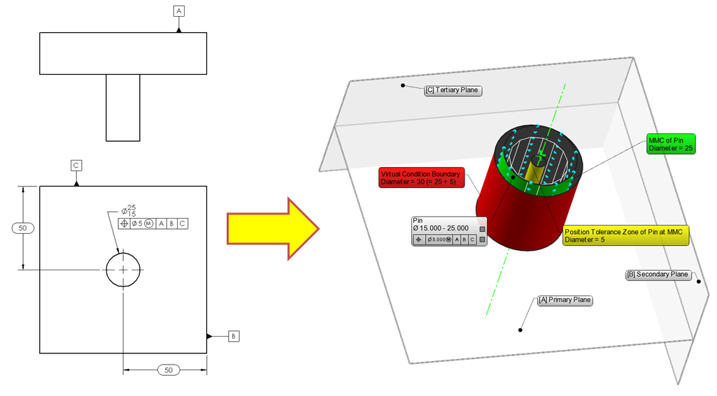
Figure 1. Geometric Dimensioning and Tolerancing: 2D versus 3D.
Geometric Dimensioning and Tolerancing concepts are often difficult to grasp at first; beginners can have quite a difficult time understanding the basic principles. One of the reasons for this difficulty is the visualization problem of 3D concepts in 2D documentation.
The goal of this blog post is to analyze the effect of the MMC (Maximum Material Condition) concept on a pin (shaft) in a 3D context with a simple example (Figure 1). Our example replicates the case in the Figure 2.15 in the ASME Y14.5-2009 standard (page 33) in a 3D context with much larger tolerances (and errors) to better visualize the concepts.
Maximum Material Condition (MMC) and Least Material Condition (LMC): Simple Definitions
MMC is the condition of a feature which contains the maximum amount of material, that is, the smallest hole or largest pin, within the stated limits of size. LMC is the condition in which there is the least amount of material, the largest hole or smallest pin, within the stated limits of size.
Figure 2. MMC and LMC concepts for a pin
In our example in the animated Figure 2, we can observe that the MMC of the pin is 25 mm, while the LMC is 15 mm.
Why Use the MMC Concept?
MMC defines the worst case condition of a part that will still guarantee, because it is still within the prescribed tolerances, the assembly between pin(s) and hole(s). When a hole is at its smallest (MMC) and a pin is at its largest condition (also MMC), we can be sure that we will still be able to assemble that part. Thus, MMC is widely used in cases where clearance fits are common.
Bonus Tolerance Concept
Figure 3. Bonus tolerance explained: As the size of the pin departs from MMC toward LMC, a bonus tolerance is added equal to the amount of that departure. Bonus tolerance equals the difference between the actual feature size and the MMC of the feature. In this case, Bonus Tolerance = MMC-LMC=25-15=10.
Clearance for assembly increases if the actual sizes of the mating features are less than their MMC. If the pin is finished at less than its MMC and closer to its LMC limits, the clearance gained can be used as a bonus tolerance for form or position. In our example (Figure 3):
Example 1: Pin diameter at Maximum Material Condition
- Pin diameter at MMC= 25
- Bonus Tolerance = 0
- Position tolerance at MMC = 5
The concept of MMC and bonus tolerance becomes much clearer if visualized in 3D.
In this first video, the center axis of the cylinder representing the pin at MMC displaces around the position tolerance zone, which is defined as a cylinder with a diameter of 5mm.
Example 2: Pin diameter at Least Material Condition
- Pin diameter at LMC= 15
- Bonus Tolerance = Pin diameter at MMC – Pin diameter at LMC = 25 – 15 = 10
- Position tolerance at LMC = 5 (Tolerance at MMC) + 10 (Bonus Tolerance) = 15
We see that when it has reached the LMC, the pin can have a larger position tolerance zone.
In the second video, the center axis of the cylinder representing the pin at LMC displaces around the position tolerance zone, which is defined as a cylinder with a diameter of 15mm. Take note that this time the allowed tolerance zone is much bigger at LMC, since we have a large bonus tolerance.
Example 3: Pin diameter somewhere in the middle
What would happen if the pin had a diameter somewhere between the LMC and MMC?
- Pin diameter = 20
- Bonus Tolerance = Pin diameter at MMC – Pin diameter = 25 – 20 = 5
- Position tolerance = 5 (Tolerance at MMC) + 5 (Bonus Tolerance) = 10
In the third video, the center axis of the cylinder representing the pin at an arbitrary dimension displaces around the position tolerance zone, which is defined as a cylinder with a diameter of 10mm. (In our example, the pin diameter is at Nominal, however this doesn’t necessarily have to be the case.)
Do you want to learn more about GD&T and how to use it to revolutionize your inspection workflows? Watch this engaging on-demand webinar.
References:
ASME Y 14.5-2009 , Dimensioning and Tolerancing. New York: American Society of Mechanical Engineers.