Recently, utility-scale wind turbines have become so large and heavy that they are manufactured and assembled in sections. While a wind turbine tower can reach a height of up to 100 m, there is a limit of 4.3 m on the diameter to pass under bridges. For easier handling and transportation, a wind turbine tower is typically manufactured in multiple sections.

Figure 1. Construction of a tower of a wind turbine: Cans > Tower Segments > Final Assembly through flanges [1]
These tower sections (or rings) are stacked on top of each other (Figure 1). Each section is a steel plate rolled into a slightly tapered circular shape and welded to form a closed ring [2]. These rings are then welded in the factory to form tower segments.
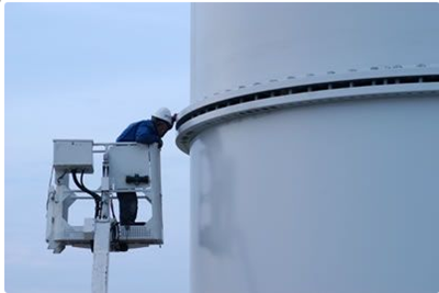
Figure 2. Use of flanges to connect wind turbine tower segments [3]
The tower segments from the factory are transported to the erection site. There, the segments are connected by flanges (Figure 2). The flange width is determined by the bolt size and varies between 100mm and 300mm [1]. The thickness depends on the required stiffness and is typically more than 100mm for a bottom flange. The bolt diameters are typically M36 to M42 but can go up to M48.
Geometric Dimensioning and Tolerancing in Wind Turbine Tower Flanges:
Manufacturing a wind turbine flange can be quite complex. Given the laborious and costly nature of the manufacturing process, application of geometric dimensioning and tolerancing principles can offer useful guidance. In the present section, we shall apply geometric dimensioning and tolerancing principles defined by the ASME standard [5] to a flange.

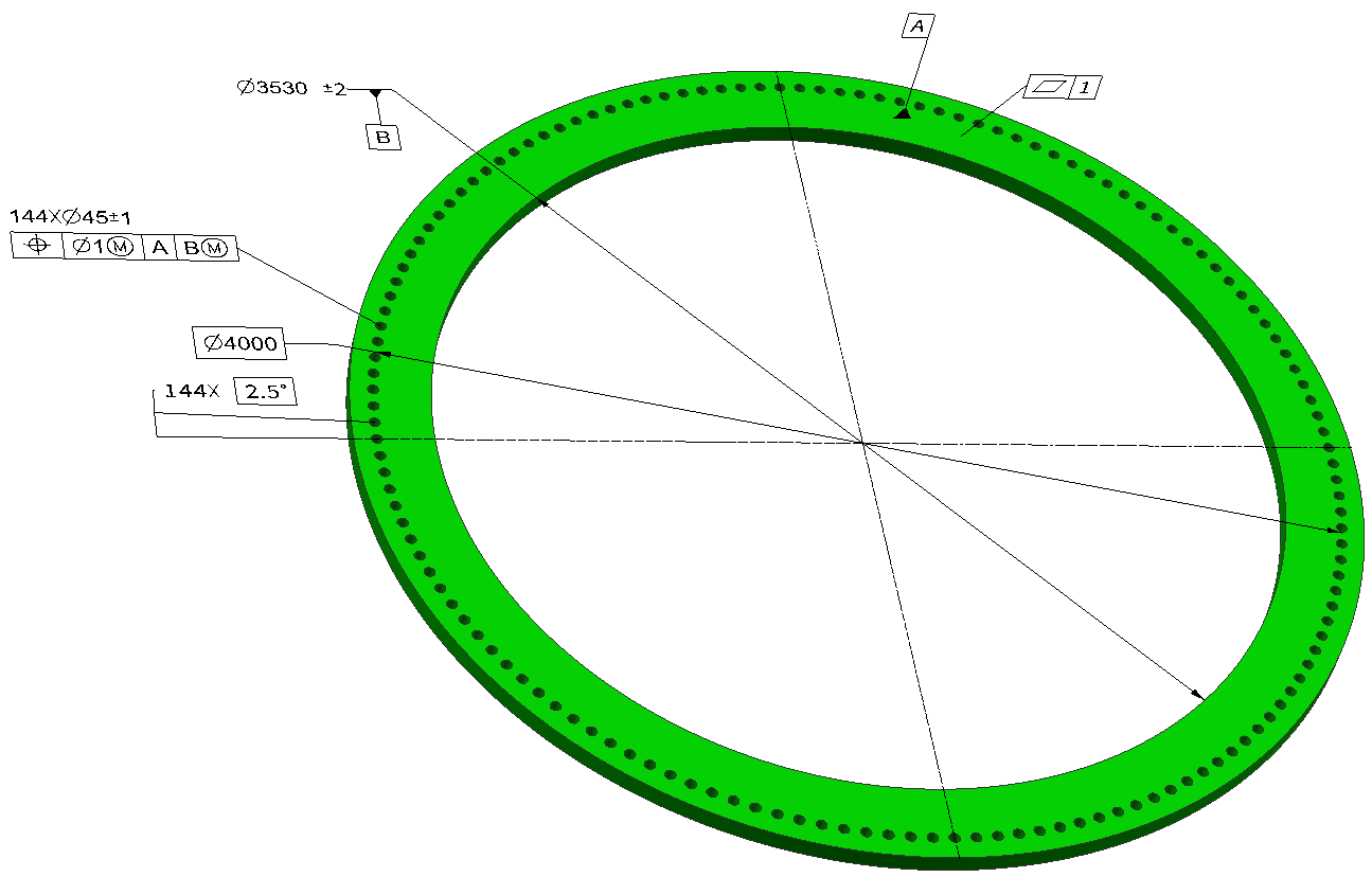
Figure 3. Wind turbine tower flange for tower base
In Figure 3, a tower flange that would fit into the foundation of a 3 MW onshore wind turbine is shown (Some details are suppressed for simplicity). As shown in the figure, the bolt circle diameter of the flange is 4000 mm, and 144 holes of 45 mm diameter are drilled into it.
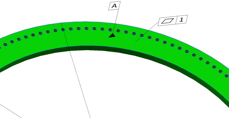
Figure 4. Flatness tolerance for primary datum surface A enables a smooth mating interface for paired flanges
The first condition for a better fit between the two flanges is the flatness of the mating surfaces. To accomplish this, a flatness tolerance of 1 mm is assigned to the datum A (Figure 4).
Then, holes are machined on the surface and the flange is welded to the tubes. Welding may introduce additional geometrical imperfections and, if the tolerances are not met for the welded flange, a second machining operation may be necessary [4]. To guarantee a good alignment of paired flanges, the bolts holes are milled into the flange using the tolerances shown in Figure 5.
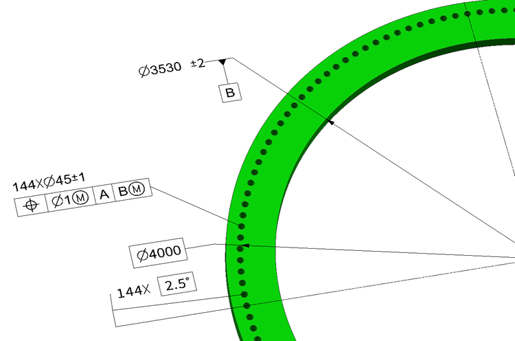
Figure 5. Position tolerances for holes on the flange enable a good alignment between paired flanges.
According to the specified tolerances on Figure 5:
Secondary datum feature (B): The inner diameter of the flange with a feature size tolerance of ± 2 mm.
Pattern of 144 holes: The holes in the pattern have a feature size tolerance of ±1 mm and a position tolerance of 1 mm at MMC with respect to datum reference frame AB(M). The position of these holes is defined with basic dimensions with respect to the datum reference frame AB(M).
References:
- Adhesive bonded towers for wind turbines, Verma A., 2011, Msc. Thesis, Delt University
- http://www.windtowersscotland.com/our-process
- http://www.cooperandturner.co.uk/markets/wind/products-and-services/tower-construction
- “Friction Connections with Slotted Holes for Wind Towers”, W. Husson, Luleå University of Technology, PhD Thesis ISSN: 1402-1757, 2008
- ASME Y 14.5-2009, Dimensioning and Tolerancing. New York: American Society of Mechanical Engineers.