In a previous post, we presented an application of geometric dimensioning and tolerancing with a wind turbine flange. In this text we will continue further, analyzing the same part with simulated points. Our objective is to observe the effects of different material modifiers on the analysis results and their advantages. For this, we will simulate measurement points on the part and then perform a GD&T analysis in BuildIT. We will then compare how the results obtained are affected by the application of different modifiers.
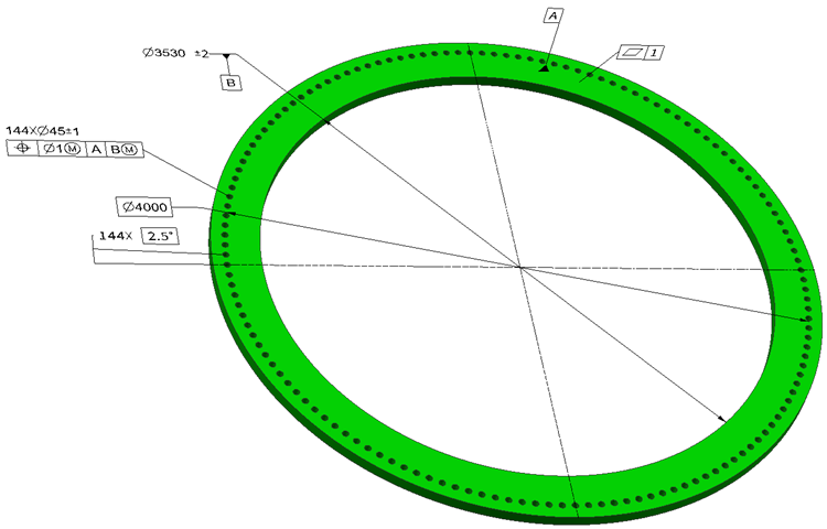
Figure 1. GD&T tolerances assigned to the wind turbine flange [1]
To summarize, the following dimensions and tolerances defined by the ASME standard [1] were applied to the flange (Figure 1):
- Primary Datum A: The upper surface of the flange: A flatness tolerance of 1 mm is assigned to datum A
- Secondary Datum B: The inner diameter of the flange with a feature size tolerance of ± 2 mm.
- Pattern of 144 holes: On Figure 1, the holes in the pattern have a feature size tolerance of ±1 mm and a position tolerance of 1 mm at MMC with respect to datum reference frame AB(M). The position of these holes is defined with basic dimensions with respect to the datum reference frame AB(M). In the following sections, we’ll be analyzing the effects of the combination of different material modifiers on the hole pattern.
Geometric Dimensioning and Tolerancing in Wind Turbine Tower Flanges:
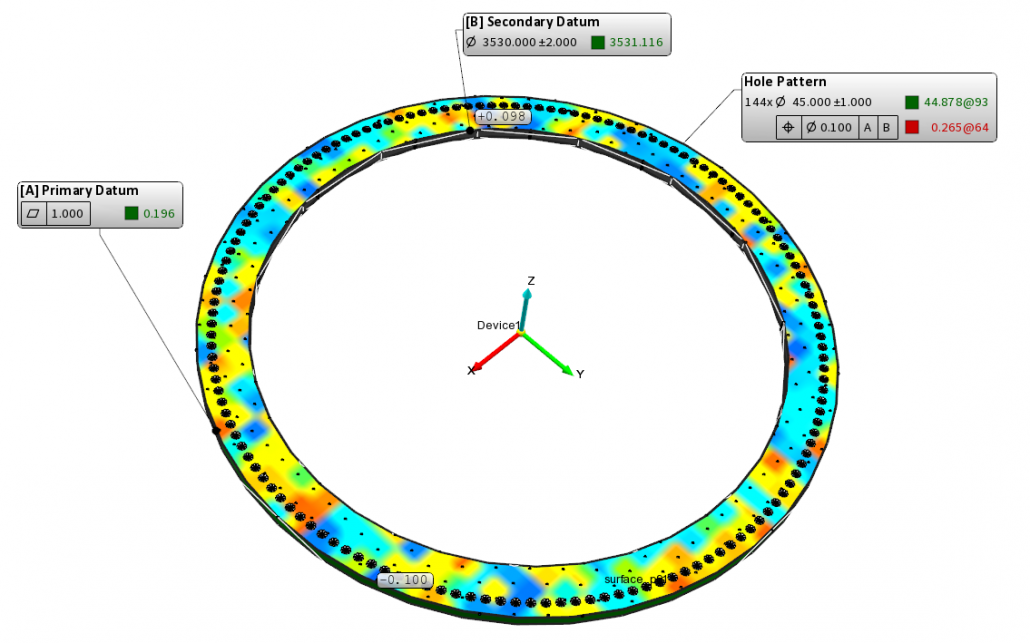
Hole Pattern Feature: Regardless of Feature Size – Datum Feature: Regardless of Material Boundary
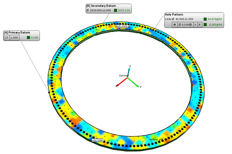
Figure 2. Wind turbine tower flange with hole pattern tolerance with RFS condition, and secondary datum with RMB condition (GD&T Analysis result – BuildIT Software)
In our first example, the position tolerance assigned to the hole pattern has no material modifier, it is regardless of feature size (Figure 2). Similarly, datum feature B has no material modifier. We simulated measurement points on the part and then performed a GD&T analysis in BuildIT metrology software.
The worst position tolerance result is at hole 64, with a position error of 0.265 mm, causing the tolerance to fail.
Hole Pattern Feature: Regardless of Feature Size – Datum Feature: Maximum Material Boundary
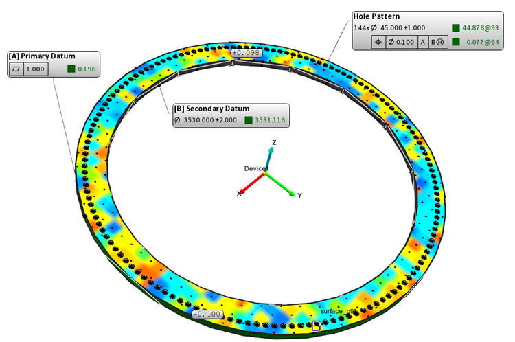
Figure 3. Wind turbine tower flange with hole pattern tolerance with RFS condition, and secondary datum with MMB condition (GD&T Analysis result – BuildIT Software)
In our second example, the position tolerance assigned to the hole pattern still has no material modifier, it is regardless of feature size (Figure 3). This time, however, datum feature B has a material modifier, which is named according to the ASME standard “maximum material boundary”. The effect of the maximum material boundary is such that it provides datum shift, giving extra “mobility” to tolerance zones. As a result, the deviation with respect to the tolerance can decrease.
With these conditions, the worst position tolerance result is again at hole 64. But this time with the material modifier applied to the datum along with the extra mobility we gained, we only have a position error of 0.077 mm, allowing the tolerance to pass.
Hole Pattern Feature: Maximum Material Condition – Datum Feature: Regardless of Material Boundary
Figure 4. Wind turbine tower flange with hole pattern tolerance with MMC, and secondary datum with RMB condition (GD&T Analysis result – BuildIT Software)
In our third example, the position tolerance assigned to the hole pattern has a maximum material condition modifier (Figure 4). This time, however, datum feature B has no material modifier.
As discussed in a previous post, Maximum Material Condition (MMC) is the condition of a feature which contains the maximum amount of material, that is, the smallest hole or largest pin, within the stated limits of size. Clearance for assembly increases if the actual sizes of the mating features depart from their MMC condition. If the hole is finished at more than its MMC and closer to its LMC limits, the clearance gained can be used as a bonus tolerance for form or position.
With these conditions, the worst position tolerance result is again at hole 64. This time, however, we have a maximum material condition on the hole. GD&T analysis results (not shown in the figure) show us that the actual diameter of the hole is 44.885 mm, which gives a 0.885 mm bonus with respect to 44 mm maximum material condition. This makes the real tolerance assigned to the hole 0.885 + 0.1 = 1.885 mm, which is considerably larger than the 0.265 mm deviation found. Thus, the tolerance passes.
Hole Pattern Feature: Maximum Material Condition – Datum Feature: Maximum Material Boundary
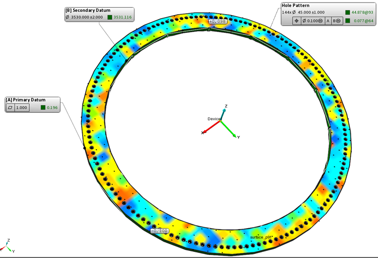
Figure 5. Wind turbine tower flange with hole pattern tolerance with MMC, and secondary datum with MMB condition (GD&T Analysis result – BuildIT Software)
In our fourth example, the position tolerance assigned to the hole pattern has a maximum material condition modifier (Figure 5), and the datum feature B also has a maximum material boundary modifier. Obviously, this is best of both worlds: We have a bonus tolerance coming from the maximum modifier on the hole, and a datum shift (tolerance zone mobility) on the datum feature. Thus, the tolerance passes easily.
These examples show the advantages of using material modifiers, either on the features or the datum features, or both. Using a modifier on a feature may help by adding a bonus tolerance while a modifier on a datum feature may provide datum shift or a tolerance mobility zone. Depending on the function of the part/feature in the assembly, defining these conditions on tolerances may help loosen these up, thus decreasing the manufacturing cost.
References
ASME Y 14.5-2009, Dimensioning and Tolerancing. New York: American Society of Mechanical Engineers.