In manufacturing and assembly, parts must be accurately and repeatably located in a well-defined reference frame to ensure consistent quality. For many automotive parts, because of the large and irregular surfaces involved, the entire surface of the feature cannot be used as a datum.
In these cases, we use datum targets to establish a datum reference frame. This post will present a possible case in the automotive industry for locating a car door with the 3-2-1 location method, using datum target areas.
For more detailed information on datum targets, you may refer to the ASME standard, section 4.24 [1].
3-2-1 Locating with Datum Target Areas
The aim of ideal location is to create an accurate and repeatable datum reference frame for the part while avoiding overconstraint. The 3-2-1 location method is widely used to attain this goal.
A free body has six degrees of freedom; linear translations in the X, Y and Z axes, as well as rotational motion around each of the X, Y and Z axes, also referred to as pitch, yaw and roll. The 3-2-1 location method is used to eliminate these degrees of freedom gradually by constraining the part to datum targets.
3 Datum Target Areas on the Primary Datum Plane
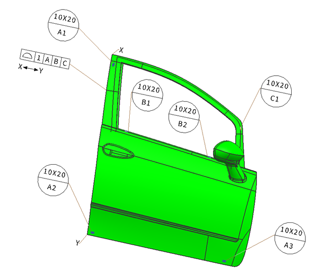
Select 3 positions for datum targets on the largest surface of the part, positioning them as far apart as possible for stability (Figure 1). Since we have a very large surface, the use of datum target areas instead of points for simulated datums is more precise. In our case, these datum target areas are designated by A1, A2 and A3.
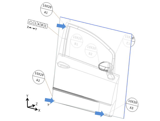
Figure 1. Primary datum plane defined by three datum target areas (A1, A2, A3)
With these three datum target areas, we have eliminated translation in the Z-axis and rotation around the X-axis (roll) and Y-axis (yaw).
2 Datum Target Areas on the Secondary Datum Plane
Select 2 points on the second largest surface of the part, perpendicular to the primary datum plane (Figure 2). Again, we make use of datum target areas instead of points for our simulated datum. These datum target areas are designated by B1 and B2.
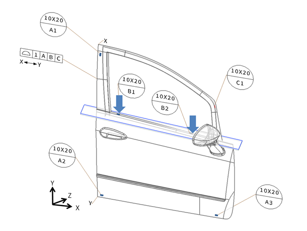
Figure 2. Secondary datum plane defined by two datum target areas (B1, B2)
With these two datum target areas, we eliminated translation in the Y-axis and rotation around the Z-axis (pitch).
1 Datum Target Area on the Tertiary Datum Plane
Select 1 datum target area on a surface perpendicular to both of the previous datum planes (Figure 3). This datum target area is designated by C1.
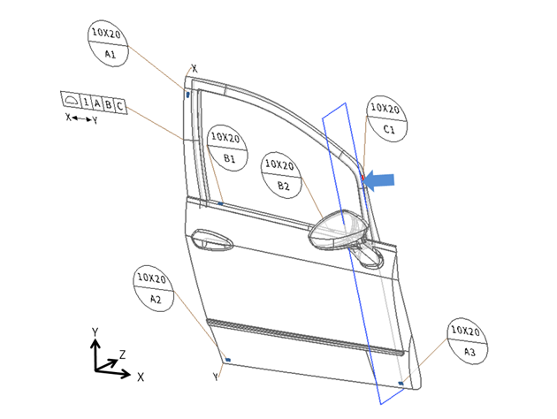
Figure 3. Tertiary datum plane defined by one target area (C1)
With this final datum target area, we eliminated the translation in the X-axis.
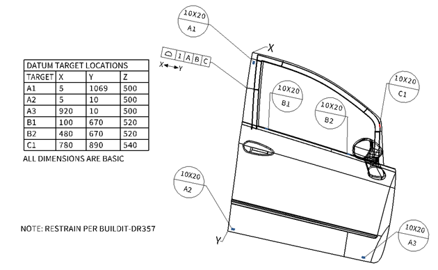
Figure 4. Final Drawing with datum target locations table
Lastly, we should define the locations of these datum target areas with respect to a defined coordinate system (Figure 4). Take note that this was just one of the possible datum reference frames we could define. Another interesting and commonplace configuration would be to use more than three datum targets on the primary datum plane. We will delve into this subject in the next blog posts.
References
ASME Y 14.5-2009, Dimensioning and Tolerancing. New York: American Society of Mechanical Engineers.
Dimensional Management Variation Handbook, John V. Liggett, 1993