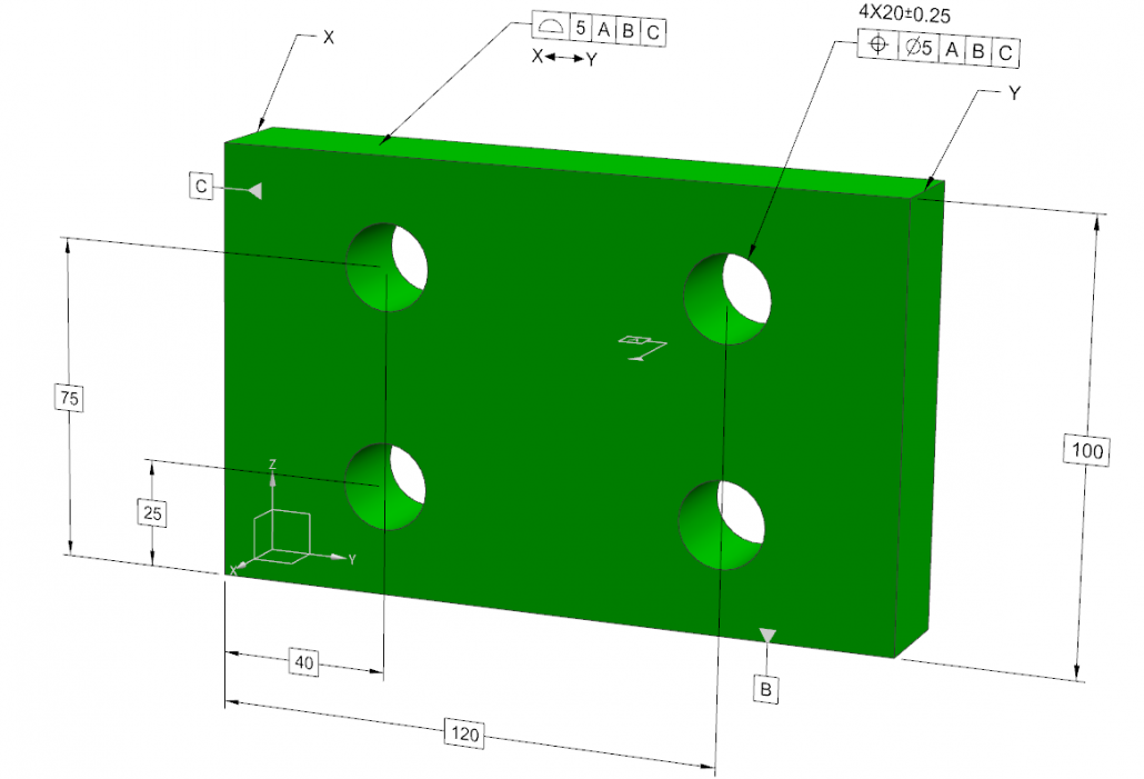
Figure 1. The tolerance zones are defined with respect to the datum reference frame (DRF – at the bottom-left corner) through basic dimensions.
A datum reference frame is a coordinate system against which the geometric dimensions and tolerances of a part are defined. The main function of the datum reference frame is to specify a foundation for the inspection of the part. It is the common coordinate system of all tolerance zones. Without this common coordinate system, product definition is unclear, rendering the inspection results unreliable.
Figure 1 shows a visual representation of this concept. The part defines position and profile tolerances with respect to a datum reference frame through basic dimensions.
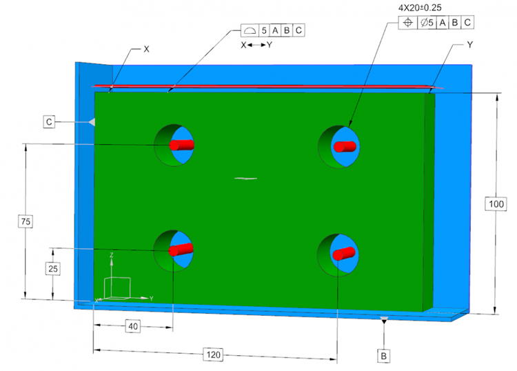
Figure 2. The tolerance zones (profile and position – in red) are defined with respect to the datum reference frame (DRF – at the bottom-left corner) through basic dimensions. The Datum reference system itself is formed by the intersection of three datum planes A-B-C (in blue)
In Figure 2, the datum reference frame at the bottom-left corner is defined by the three orthogonal datum planes, A, B and C (in blue). Using this datum reference system as the common origin, the basic dimensions (the dimensions inside rectangular boxes) define the tolerance zones (in red) for position and profile tolerances. This means that once the part is immobilized through 3 datum planes, the center axes of the holes should be inside these tolerance zones located by 4 vertical and horizontal basic dimensions, 75-25 and 40-120 mm, respectively. This zone is defined by a cylinder of 5mm diameter.
Similarly, the upper surface of the part should be between the two planes defining the profile tolerance zone located by a basic dimension of 100 mm. The distance between these two planes is 5 mm.
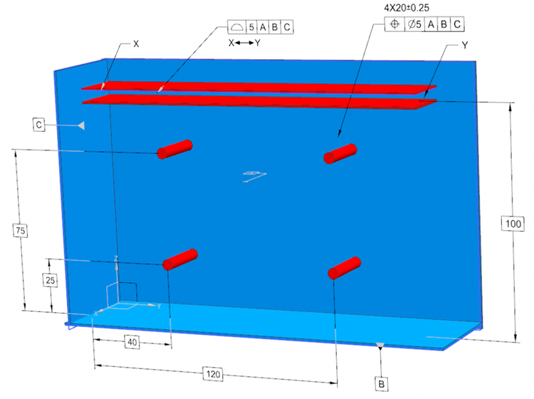
Figure 3. The same figure as Figure 3, without the part itself. The tolerance zones (profile and position – in red) are defined with respect to datum reference frame (DRF – at the bottom-left corner) through basic dimensions. The Datum reference system itself is formed by the intersection of three datum planes A-B-C (in blue).
This blog post showed just a simple example of a datum reference frame and the related specification of tolerances for educative purposes. We will discuss more involved applications in the coming posts.