Technology is changing the world day-by-day, and the construction industry is no exception. Things like building information modeling (BIM), laser scanners, and 3D modeling are changing the landscape of how work is being completed — and saving companies both time and money in the long-run.
Rodney Roebuck, CEO of Roebuck Contracting, has been in the industry for 27 years and got his start in the HVAC industry. In that time, he’s seen numerous innovations come to light — including building automation, CAD, and BIM — and more traditional methods of work fall by the wayside.
“Whenever we were assigned the task of modeling an asset or space, many hours were spent taking measurements. We used laser tapes, tape measures, and measuring wheels to sketch out our project on graph paper before sitting down at the workstations to model,” Roebuck says. “[That’s when we] … started researching laser scanning equipment. We watched several videos and read articles about the technology that seemed almost magical at the time.”
Roebuck and his BIM manager at the time decided to reach out to FARO® Technologies for a demonstration of their laser scanners. After the FARO Account Manager scanned their conference room and demonstrated just how quickly precise measurements could be acquired, they were sold. However, they still needed to decide which scanner and software were right for their needs.

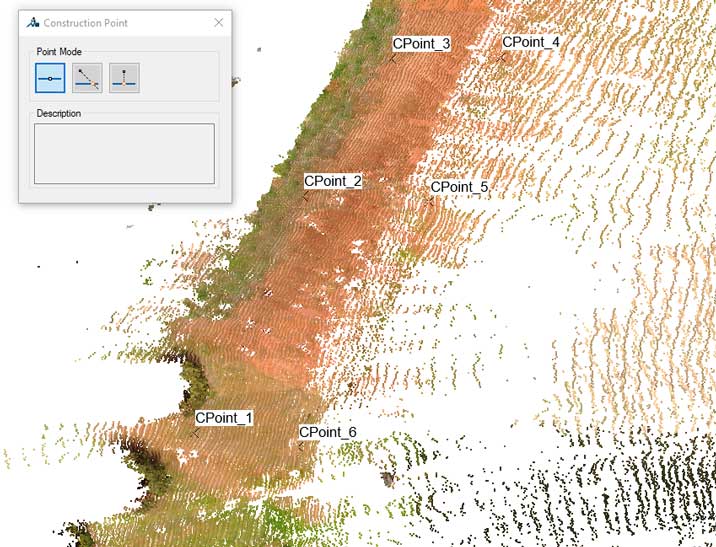
Figure 1. The Topo Surface command in PointSense facilitates the building of Revit site plans from scan data.
After some discussion, they decided on the FARO FocusM 70 Laser Scanner and PointSense Software Suite.
“We landed on the FARO FocusM 70 and the PointSense Suite as being the best fit for our needs and goals,” Roebuck says. “The M70 had the acquisition range we thought would fit most of our projects, and the PointSense Suite allowed us to take the point clouds and automate the extraction of walls, pipes, and planes along with topography and more. The price for the scanner and software was at a point where the ROI made good sense financially.” The speed of using the laser scanner compared to the previous methods of data capture was incomparable for Roebuck.
“The time savings of field measurement versus laser scanning is not quantifiable in my opinion, dimensions gained from one site visit consisting of several scans dwarf the data of weeks of conventional measurement gathering.”
-Rodney Roebuck, CEO, Roebuck Contracting
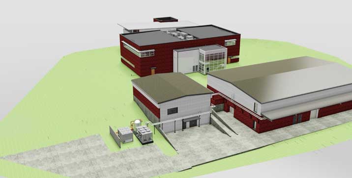
Figure 2. Accurate models built from laser scans allow customers to visualize the finished project.
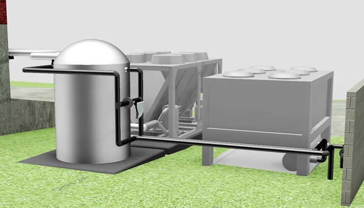
Figure 3. Existing equipment was modeled from the scans, and new equipment is added with piping and valves.
Cooling Down
Roebuck Contracting’s most recent project is the installation of an air-cooled chiller and the replacement of several 20-year-old air handling units and pad-mounted condensers at a training facility campus just outside of Atlanta. Made up of numerous buildings, the campus already has one building being serviced by an air-cooled chiller.
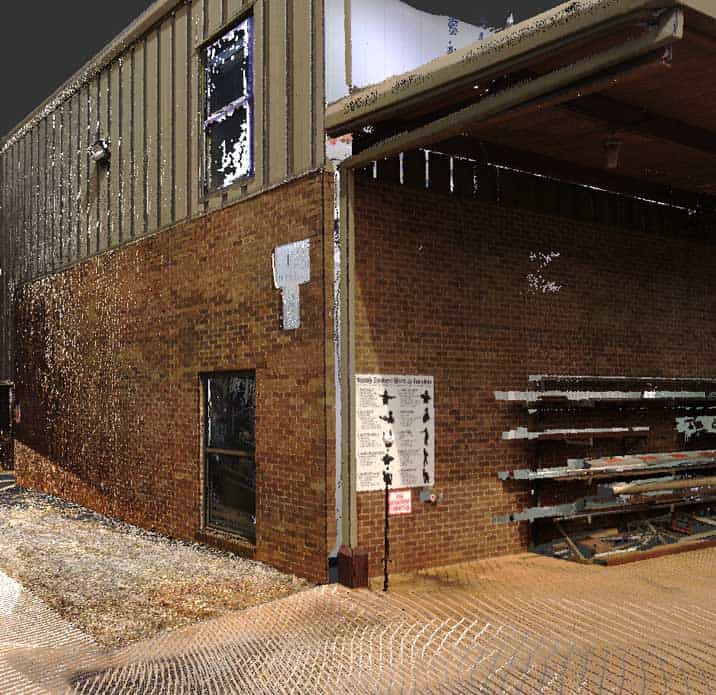
Figure 4. From one laser scan, all dimensions are available to plan out piping and conduit routes.
The goal of the new chiller installation is to configure the pipe and valve arrangements so as to offer a level of redundancy to the existing air-cooled machine, as well as replace the low SEER-rated equipment with a higher efficiency method of cooling two other buildings.
Roebuck was directed to design the chilled water system and route the piping in the most economical and aesthetically-pleasing way possible. However, Roebuck’s client for the project didn’t have an accurate up-to-date set of drawings for the two buildings.
That’s when the FARO FocusM 70 Laser Scanner came into play.
“The scanner has been used as the first boots-on-the-ground for this modeling project,” Roebuck says. “The inside and outside of the buildings have been scanned, including ceiling plenums. The processing and registration of the scans have been completed, and the Autodesk® ReCap™ file is linked into the Revit® project.”
Roebuck used the PointSense software to create the topography for the Revit® Site Plan. He then moves the point cloud to match elevations if he didn’t scan with the GPS on. Once the elevation is correct, other levels such as tops of walls, slab heights, and roofs are set, and he then rotates the cloud to the “Project North” that he wants to draw in. After enough PointSense Construction Points are created to suit the project, he lets PointSense build the topography with its Topo Surface command.
Challenge Accepted
One of the biggest challenges of the project was the routing of chilled water lines from where the new chiller was located to the new chilled water air handlers, which were located just a few hundred feet away.
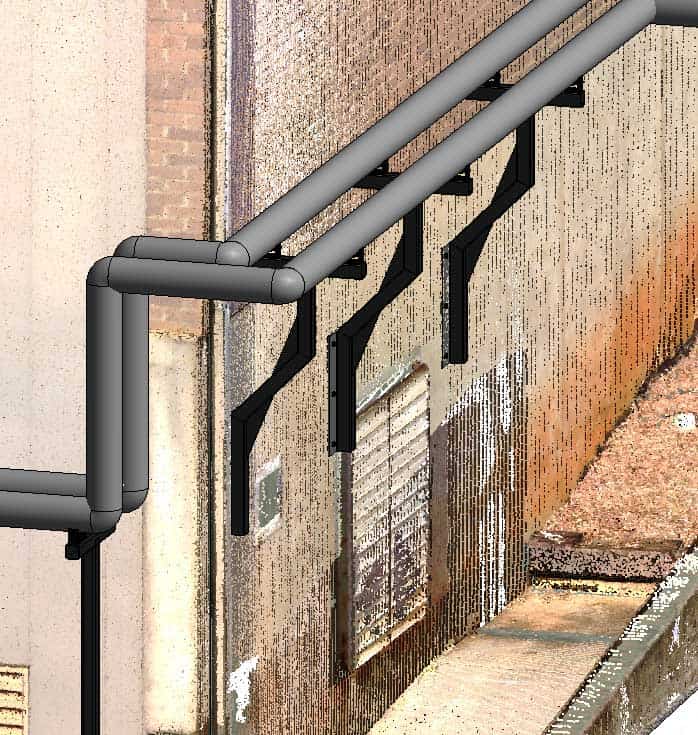
Figure 5. Keeping a clear walk path required designing wall mounted piping supports.
Roebuck’s initial discussions with his customer had the piping going through the plenums of both buildings to be served by the chiller. However, once the site was scanned and the plenum spaces were assessed, they realized that the piping would have to run externally to the building. The biggest problem being that there were I-beams and ducts that would have made the pipe runs both difficult and expensive.
The external piping would have to cross a walkway between the two buildings and would need to be at an elevation with plenty of head clearance. The customer also didn’t want the field constructed strut type bracket on the side of the building.
Using the point cloud to measure and model the building, Roebuck and his team designed a pipe support system that they could have a machine shop build and powder coat.
“By using the FARO FocusM 70 Laser Scanner, we were able to design the piping supports for construction by a machine shop and be shipped to the site,” Roebuck says. “We were able to accurately route the piping and derive the total equivalent length for chilled water pump sizing, and we were able to erase equipment that’s being replaced from the point cloud and fit new Revit equipment into the voids to check clearances.”
Not only did the laser scanner help provide the necessary steps to get the piping supports built, but it also cut down the time needed to complete the project. “The data acquired through the use of the laser scanner improved our modeling accuracy and efficiency and saved weeks of labor in field measuring time. All of the scanning necessary to model the project took about 20 hours” he says.
When asked if he would recommend the FARO FocusM 70 Laser Scanner, Roebuck enthusiastically answered with a resounding, “Definitely.” He adds, “We will be using the scanner with every opportunity we are given due to the proven reliability the point clouds offer in measurement, visualization, and time savings.”
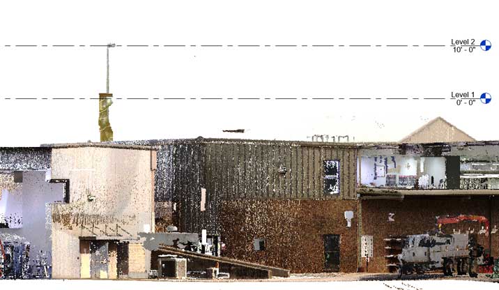
Figure 6. The scans come into Revit needing alignment and level adjustments for ease of modeling.
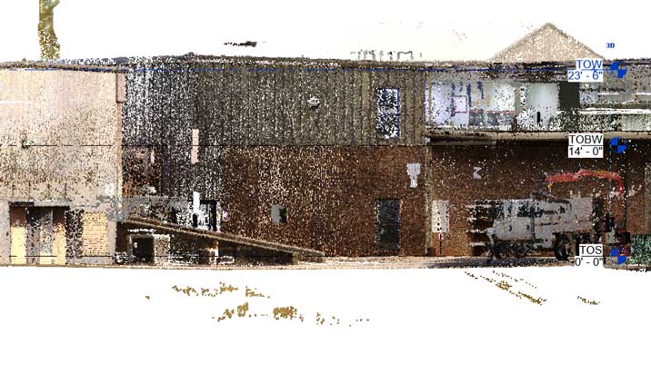
Figure 7. The building slab is aligned to the 0’ 0” level so that spot elevation references are accurate in the drawing set.
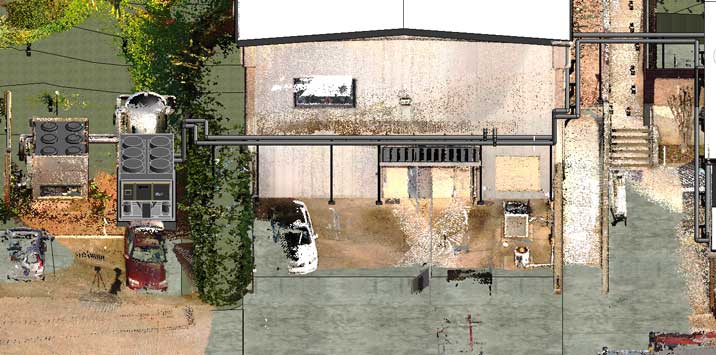
Figure 8. The new chiller and piping are show here with the model and point cloud turned on.