Step 1: Let’s begin with proper setup.
When setting up the FARO® Laser Tracker Vantage, I always ask myself how will the environment effect my measurements relative to my tolerances? Is vibration an issue such as forklifts or running machinery nearby?
If the tracker is mounted in an area with high vibration, something known as drift can occur. Drift is caused by the tracker physically moving away from its origin. Is the temperature consistent throughout the area I plan to measure?
A common culprit is open factory doors. When the tracker laser passes through different temperature zones it behaves the way it would if it shined through a panel of glass and bends slightly, the greater the temperature deviations the thicker the pane of glass. High humidity also affects the tracker. The tracker measures the relative humidity to compensate for its affect on the index of refraction of the laser beam in order to maintain an accurate distance measurement from the tracker to the target. However, the tracker is meant to be used in a non-condensing environment. If the tracker is being used where condensation can form on the SMR and / or the trackers optics, tracking can be affected because the condensation will reduce the amount of light being reflected off the SMR (if the condensation is on the SMR). If the condensation is on the trackers optics, it will affect the amount of light emitted from the tracker as well as increase the amount of light lost when re-entering the tracker off the SMR which will also affect its ability to stay locked onto an SMR. So you can imagine how vibration, temperature, and humidity can play a key role in determining where to setup the tracker and if the measurements can be considered valid. Always be sure to allow the tracker time for the warm up and immediately after, run the selfcomp or quickcomp routine (depending on which you are using) before starting any measurements. I usually run the quickcomp every 2 hours to compensate for the environment changes throughout the day. Also, by mounting several pucks around the area and measuring points, you can Digital Read Out to these points at any time to check for drift and if you notice drift you can easily correct it by performing the move device operation.
Step 2
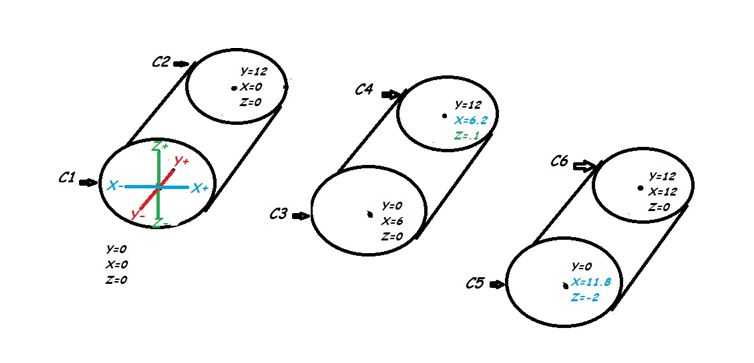
With most roll alignments, the goal is usually to align to a reference, such as monuments or perhaps to a drive roll. This is where I would create a coordinate system. Next, measure a plane and circle on both ends of each roll. You want to measure circles because they are point reducible which makes it easy to verify if the rolls are in or out based on the coordinate value of the circles center point. Based on how the coordinate system is setup, I normally make Z+ represent my elevation, X+ to be the distance between rolls, and Y+ to be the length of each roll. By simply looking at the X and Z values of each circle, I can check to see if the rolls are level and equally spaced. Take a look at the sample below.
If you notice circle C4 the X value is 6.2 and the Z value is set to 0.1. So to correct this we would simply move the C4 end of the roll into the –X direction by 0.2 and down in the –Z direction by 0.1. You would simply repeat this for the rest of the rolls.
So with proper setup and the use of coordinate systems, roll alignments can be performed accurately and save a lot of time and labor cost in the long run.